Let’s make a bootloader for STM32, part 2
Napisano dnia 31.01.2021 r. o godzinie 8:00
Autor: Piotr Sperka
Introduction
Welcome to the second part of the series on creating a bootloader for the STM32 microcontroller. In the first part, I introduced you to what a bootloader is and how it works. We also wrote a basic function that makes it possible to reallocate the interrupt vector and make a jump to your application. Now it’s time to support software updates. This means FLASH memory programming. In addition, I will show you an easy way to check if the user’s application is loaded at all.
FLASH basics
Since we use HAL libraries in the bootloader project, flash programming is not particularly difficult. We must remember only one important thing. Due to the nature of flash memory, before uploading a new program, we must erase it first. We cannot simply overwrite existing content, because we will expose ourselves to large amounts of errors.
Why? Well, the erased FLASH memory has the value of each byte set to 0xFF, i.e. binary to 0b11111111. When saving data to memory, we can only set the selected ones to zeros, but not the other way around. Therefore, if we do not clear the memory beforehand and to the cell containing the byte 0b11110000 we decide to write the byte 0b00001111, we will get 0b00000000 – which is definitely not what we wanted. There is one more catch – in the case of the vast majority of FLASH memories, we cannot clean only the selected byte. It has to be the entire page or sector. The size of such a page or sector varies from several hundred bytes to several hundred kilobytes.
Armed with the above knowledge, we can say what functions we need to create:
- Clearing the memory (selected pages or sectors – depending on the microcontroller).
- Memory programming.
- Memory reading (for example, to download a backup).
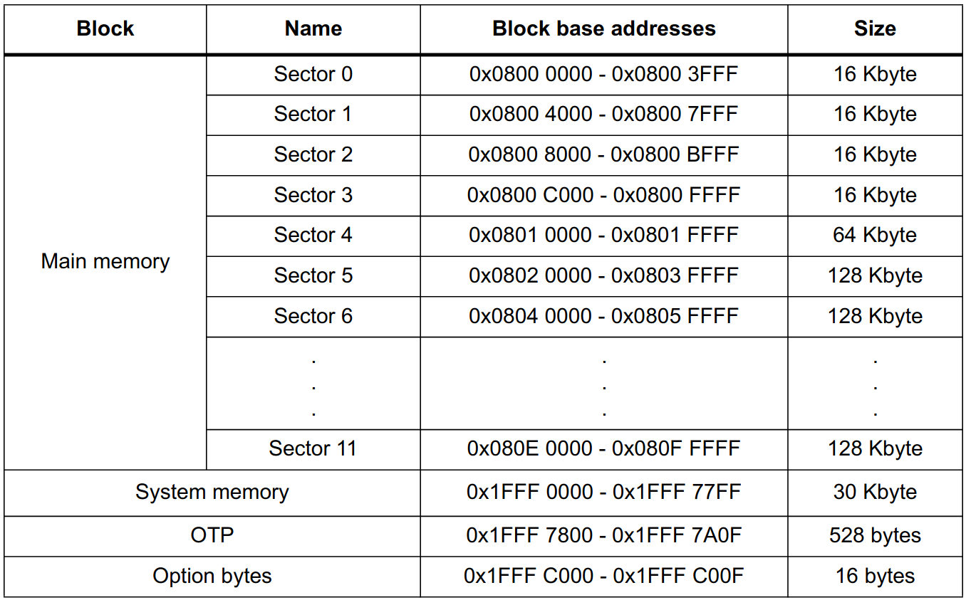
Flash memory organization for STM32F207 taken from the documentation
Clearing the memory
Let’s deal with clearing the FLASH memory first. Our microcontroller – STM32F207VCT6 – is equipped with 256 kB of FLASH memory. That means we are interested in sectors from 0 to 5 from the table above. In the case of other families or microcontrollers, there will be differences. If you use a microcontroller from another family (e.g. STM32F1 or STM32F4), you have to search the documentation. Since we have allocated 64 kB of memory for the bootloader, it is in sectors 0, 1, 2 and 3. The user’s application can occupy sectors 4 and 5, and now we will deal with clearing them.
By the way, there is one more issue. For the bootloader, we should allocate a memory area matched to the total size of one or more sectors. If we decided to allocate, for example, 24 kB of memory to the bootloader, i.e. sector zero and half of the first, we would not be able to properly replace the user’s application. As I wrote earlier, before saving new data, we need to clear the sector. If there were both bootloader and user application code in the first sector, clearing it would damage the bootloader. And now let’s move on to clearing the sectors we are interested in.
uint8_t EraseUserApplication() {
    HAL_StatusTypeDef success = HAL_ERROR;
    uint32_t errorSector = 0;

    if (HAL_FLASH_Unlock() == HAL_OK) {
        FLASH_EraseInitTypeDef eraseInit = {0};
        eraseInit.NbSectors = 2; // Count of sectors to erase
        eraseInit.Sector = FLASH_SECTOR_4; // First sector to erase
        eraseInit.VoltageRange = FLASH_VOLTAGE_RANGE_3; // Device operating range: 2.7V to 3.6V
        eraseInit.TypeErase = FLASH_TYPEERASE_SECTORS;

        success = HAL_FLASHEx_Erase(&eraseInit, &errorSector);

        HAL_FLASH_Lock();
    }

    return success == HAL_OK ? 1 : 0;
}
At the beginning, we need to unlock writing and clearing the FLASH memory. We do this by calling the HAL_FLASH_Unlock function. If the operation is successful, we can clear the sectors. In this case, they are sectors 4 and 5. Finally, we lock writing FLASH memory again.
Programming and reading the memory
While erasing memory varies from family to family, programming and reading are the same. For writing memory, we will use the HAL library. The reading is the simplest. We just need to set the pointer, and we can read the data in the same way as from RAM. Below there are two functions. The first one allows you to program a selected area of FLASH memory. The second one uses the hypothetical SendByte() function to read and send a copy of the entire user application.
uint8_t WriteUserApplication(uint32_t* data, uint32_t dataSize, uint32_t offset) {
    if (HAL_FLASH_Unlock() == HAL_OK) {
        for (int i = 0; i < dataSize; i++) {
            HAL_StatusTypeDef success = HAL_FLASH_Program(FLASH_TYPEPROGRAM_WORD, APP_ADDRESS + offset + (i * 4), data[i]);

            if (success != HAL_OK) {
                HAL_FLASH_Lock();
                return 0;
            }
        }

        HAL_FLASH_Lock();
    } else {
        return 0;
    }

    return 1;
}
void SendBackup() {
    uint8_t* app = (uint8_t *) (APP_ADDRESS);

    // Send 192 kB of user application
    for (int i = 0; i < 192 * 1024; i++) {
        SendByte(app[i]);
    }
}
Of course, treat the above functions as sketches or prototypes. In the third part of the article, we will refine them and create a small PC application that can upload and download user’s application.
Is there anywhere to jump?
In terms of jumping to the user’s application, we can ask ourselves one more question – is there anything to jump to? After all, it may happen that only the bootloader will be uploaded. In my opinion, the easiest way is to read the first word of the user’s application (four bytes). Normally, there is the initial value of the stack pointer. In the case of programs written in C, it should point to the end of RAM.
Thanks to this, we can create a simple function. It will return 1 in the case when the first word of the user’s application is correct, and 0 otherwise. If there is nothing to jump to, we know that we have to wait for the user to upload the application. In other words, we stay in the bootloader mode. You can also inform user that the application is missing. Below, you will find an example implementation that is based on a comparison of the first four bytes of the bootloader and the user’s application:
uint8_t UserApplicationExists() {
    uint32_t bootloaderMspValue = *(uint32_t *) (FLASH_BASE);
    uint32_t appMspValue = *(uint32_t *) (APP_ADDRESS);

    return appMspValue == bootloaderMspValue ? 1 : 0;
}
We can use it as described below. In this example, if no user application is found, the LED connected to pin PE7 will start flashing at 5 Hz. You can try it out by clearing the user’s application. To do this, you need to connect the PB13 pin to the ground and reset the microcontroller.
while (1) {
    if (HAL_GPIO_ReadPin(GPIOB, GPIO_PIN_13) == GPIO_PIN_RESET) {
        EraseUserApplication();
    }

    for (int i = 0; i < 6; i++) {
        HAL_GPIO_TogglePin(GPIOE, GPIO_PIN_7);
        HAL_Delay(500);
    }

    if (UserApplicationExists()) {
        JumpToApplication();
    } else {
        while (1) {
            HAL_GPIO_TogglePin(GPIOE, GPIO_PIN_7);
            HAL_Delay(100);
        }
    }
}
Summary
We have created a simple skeleton of user’s application and bootloader. The bootloader contains all the most important functions: it checks whether the user’s application is uploaded and jumps into it, and also allows programming and reading FLASH memory. In the last part of the series, I will present a very simple example using this skeleton and the chosen way of communication to create a complete bootloader.
The entire code, which was created on the basis of today’s article, is available HERE.
And as always: if you have any questions or comments, don’t hesitate to email me. I invite you to the third, last part.