Let’s make a bootloader for STM32, part 1
Napisano dnia 24.01.2021 r. o godzinie 8:00
Autor: Piotr Sperka
Introduction
I became interested how to make a bootloader for STM32 when the project I was making at the time required it. At the beginning, I wanted to use an existing solution. Unfortunately, due to the specificity of the project, every free solution available was insufficient. At this time, I decided to explore the issue in more detail and create the bootloader by myself. Some time later, I decided that this topic is worth creating a series of two or three articles. They will lead to the creation of a universal template for the bootloader and applications that you can customize exactly to your needs. In fact, they were supposed to be created nearly two years ago… Well, as they say, better late than never. But let’s start from basics…
What is a bootloader?
You may ask: what is a bootloader? Well, in short, a bootloader is a program that runs another program. It can also provide various other functionalities, such as creating a backup or updating software without any additional hardware (programmer). In my case, this was the main feature that I wanted to use. Here’s what we want to achieve: when the power is turned on, the microcontroller begins to execute a program located at the beginning of the memory. This is our bootloader. Under normal conditions, the only task of the bootloader is to load and run the user’s application.
In STM32 (as probably in most microcontrollers), the bootloader and the user’s application are in the same FLASH memory. It means that under normal conditions, the task of the bootloader is to make a jump to the further part of the memory. This is where the user’s application is located. However, when appropriate circumstances (for example, pressing a button, receiving the appropriate command, etc.) occur, the bootloader should:
- Download the new version of the software (user’s application) through the selected interface. This can be, for example, UART, SPI, SD card, Ethernet, USB, or any other desired way.
- Upload it to the FLASH memory in the appropriate place, replacing the previous version of the user application.
- Optionally verify if the uploaded program is correctly written.
- Run the application, which means jumping to its beginning.
In the figure below, I schematically presented how the memory organization can look like in the case of standard software for a microcontroller, as well as in the case of using a bootloader.
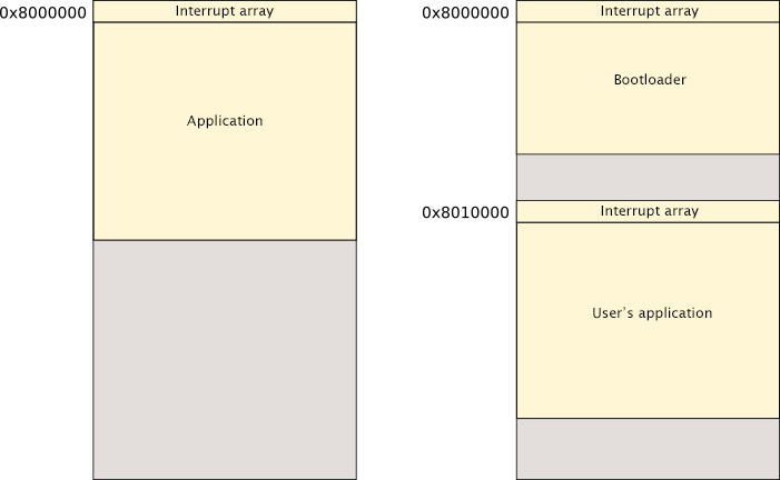
Since the bootloader is uploaded once (at least in final product), using a programmer, and then we do not update it (after giving the device to the end user), it must be written quite neatly. Of course, you can embed the option to update the bootloader, but in this article we focus on a simple solution. It is also worth trying to make the amount of memory occupied by the bootloader as small as possible. It is quite obvious – the larger the bootloader, the less space will remain for the user’s application.
More details…
Before I move on to further issues, you need to know a few additional details about the construction of the microcontroller software. As you surely know, when you start, the microcontroller begins to execute the program from the initial address in the program’s memory. Most often, however, the program itself is located a little further (the beginning of the main() function in the case of C/C++). At the very beginning of the memory there are interrupt vectors. These are pointers for functions (address in memory to which microcontroller should jump), which are called when certain interrupt occurs. It will be much easier for you to understand this issue if you know how the CPU works. Anyway, I’m going to explain the matter as simply as possible.
How does it work in practice? Let’s say that the interrupt vector of the SysTick timer is located at the address of the 0x003C in the interrupt array, and the four-byte value of the 0x00010020 is written there. If this interrupt occurs, the microcontroller calls the function located at 0x00010020. In other words, it will make a jump to the mentioned address. This is very important information for us, because we do not want the interrupt functions defined in the bootloader to be performed after starting the user’s application.
In the case of STM32, at the address 0x0000 there is a value that should be entered into the SP (Stack Pointer) register. At the 0x0004 address there is placed the first interrupt vector – Reset vector. This is the address that microcontroller jumps after reset. As it turns out, both of these addresses will be very important to us when making a jump to the user’s application. In addition, I must also mention the VTOR register, which will also be very important to us. It allows you to reallocate an interrupt vector array to a different starting address. In other words, it determines the initial address of the interrupt array.
Based on the previous example, let’s assume that we enter the value of 0x00010000 into VTOR. Then, when a SysTick interrupt occurs, the microcontroller will not look for the function address at the 0x003C address in memory. It will look at the 0x0001003C address instead. I hope that even if at this point not everything is clear, it will become clear after moving on to the examples.
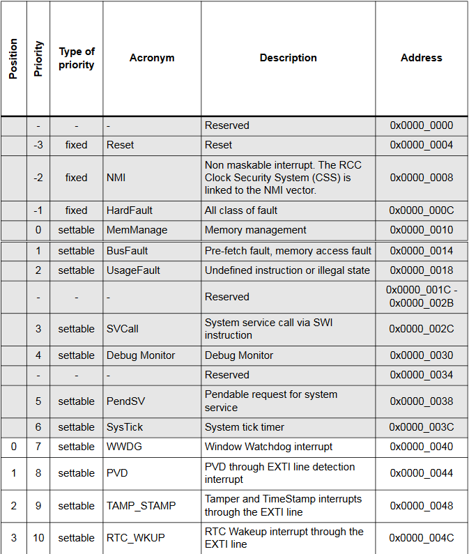
Part of the interrupt vector array for STM32F2 taken from the documentation
What are we going to do today?
The task of writing a bootloader is both easy and difficult. Easy, because compared to various programs, its operation is rather simple. Difficult, because among the available descriptions and sources, the bootloader and its operation is relatively rarely discussed. In the first part of this series, we will create foundations for further development. We will create two applications: bootloader and user’s application. The task of the bootloader will be to flash the LED three times and make a jump to the user application. The task of the user’s application will be to flash another LED. You may think that this is absolutely trivial, but a solid foundation is the most important thing in any project. Having such basics and a working template, we will be able to easily extend the functionality of the bootloader.
In the prototype, I used a board with an STM32F207VCT6 microcontroller. I wrote the software in the JetBrains CLion environment along with the arm-none-eabi toolchain and STM32CubeMx. This set uses CMake, so it should easily integrate with many other IDEs.
Let’s create something!
Let’s start by creating two projects for our microcontroller which compile successfully. Since both projects will be expanded over time, I used the HAL library. In the basic version, the only configuration made in STM32CubeMx was to set the pins controlling the LEDs as outputs. In my case, in both of them I flashed one of the two LEDs with different frequency:
while (1) {
    HAL_GPIO_TogglePin(GPIOE, GPIO_PIN_7);
    HAL_Delay(500);
}
while (1) {
    HAL_GPIO_TogglePin(GPIOE, GPIO_PIN_8);
    HAL_Delay(250);
}
If after programming the system LED flashes as expected, the first step is behind us. At this point, of course, uploading the second program overwrites the first. It’s time to change that. To do this, the second program (user’s application) must be transferred to the further part of the memory. First of all, we need to modify the linker script in both programs. Since the bootloader will be expanded, I decided to allocate the first 64kb of memory for it. In the case of the bootloader, I modified the line in the STM32F207VCTX_FLASH.ld file:
FLASH (rx) : ORIGIN = 0x8000000, LENGTH = 256K
to:
FLASH (rx) : ORIGIN = 0x8000000, LENGTH = 64K
In the case of a user’s application, we want to allocate the rest of the available memory. In this case: 256kb – 64kb = 192kb. We also want to move it away from the initial address by 64kb (where will be bootloader). In a hexadecimal system 64k is 0x10000. To achieve this, we modify the same line as above in the user’s application project to:
FLASH (rx) : ORIGIN = 0x8010000, LENGTH = 192K
After this modification, the linker should properly place our program in memory. I mentioned earlier the interrupt vector array, and the fact that we will reallocate it. In order for everything to work properly, in addition to the offset in the VTOR registry, you must also indicate the offset of the interrupt array in the /Core/Src/system_stm32f2xx.c file. We change line:
#define VECT_TAB_OFFSET 0x00000000U
to:
#define VECT_TAB_OFFSET 0x00010000U
We also need to uncomment the line:
#define USER_VECT_TAB_ADDRESS
Now, if we compile both programs, regardless of which one we upload last, microcontroller should always execute the bootloader code.
Jump to the user’s application
Since we already have a properly placed both the bootloader and a user’s application, we can take care of making a jump from the bootloader to the user’s application. To do this correctly, we need to do a few things:
- Deinitialize all peripherals used in the bootloader.
- Reset the SysTick timer.
- Set the interrupt vector array offset (SCB→VTOR).
- Set the stack pointer (value from the interrupt array from the 0x0000 address [relative to the beginning of the user’s application]).
- Jump to the beginning (entry point) of the user’s application, i.e. to the address indicated by the Reset vector. As I mentioned earlier, it is located at the address of 0x0004 relative to the beginning of the program.
The code that performs the above actions looks like this:
#define APP_ADDRESS (uint32_t)0x08010000

typedef void (*pFunction)(void);
void JumpToAddress(uint32_t addr) {
    uint32_t JumpAddress = *(uint32_t *) (addr + 4);
    pFunction Jump = (pFunction) JumpAddress;

    HAL_RCC_DeInit();
    HAL_DeInit();
    SysTick->CTRL = 0;
    SysTick->LOAD = 0;
    SysTick->VAL = 0;

    SCB->VTOR = addr;
    __set_MSP(*(uint32_t *) addr);

    Jump();
}

void JumpToApplication() {
    JumpToAddress(APP_ADDRESS);
}
As a parameter of the function, we give the address of the beginning of the user’s application. In this case the 0x8010000. Now, if we modify the loop which is flashing LED in the bootloader like this:
while (1) {
    for (int i = 0; i < 6; i++) {
        HAL_GPIO_TogglePin(GPIOE, GPIO_PIN_7);
        HAL_Delay(500);
    }

    JumpToApplication();
}
the program should blink it three times and then start executing the user application. Which flashes another LED… At this point, we can easily modify both the bootloader and the user’s application. Debugging also works without any issues.
Summary
In conclusion, in today’s article I showed a general concept of how the bootloader works. I used a microcontroller from the STM32 family for this, but this concept will be similar for many other microcontrollers. I also showed you how you can make the jump to the user’s application. In the next part of the series, we will deal with a very important function of the bootloader. It is programming the user’s application to FLASH memory.
The entire code that I created on the basis of today’s article is available HERE.
And as always: if you have any questions or comments, don’t hesitate to email me. Part two is available HERE.